Arithmetic logic unit (ALU) consists of the following blocks:
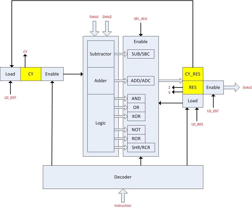
- Red labels are used for external connections (with computer’s bus).
- Yellow rectangles are used for storing data
- Other rectangles contain logic inside
Calculations performed with ALU contain the following steps:
- Decode instruction (outside this scheme) and select input registers to data bus
- Decode instruction code by the Decoder and optionally select CY as input
- Switch Adder, Subtractor or Logic output to result storage input
- Latch the result into the result holding register
- Reset destination register
- Switch result output and destination input on data bus
- Latch data into destination register and CY flag into CY storage
These actions are performed by the following signals:

ALU requires 5 clock ticks to calculate, latch, and feed the result to the bus:
- Tick 1 - LD_RES resets result register, and SEL_ALU1/2 enables ALU inputs.
- Tick 2 - raising SEL_ALU and lowering LD_RES selects the specific ALU block and latches calculation result into the result register.
- Tick 3 - pause to let SEL_ALU down. ALU stops calculating then and result register becomes stable.
- Tick 4 - LD_DST is set to high. It resets destination register and CY “register” which is situated in the ALU.
- Tick 5 - SEL_RES puts the value of the result register onto the data bus 1. CY storage receives new value too.
ALU also has CY, S, and Z output flags that are used for conditional jumps execution.
Adder block
Adder has “dual rail” design which was invented by Konrad Zuse for his Z3 computer. Adder block takes two arguments, CY, and ~CY as an input and produces 8 bits of sum and one bit of Carry.

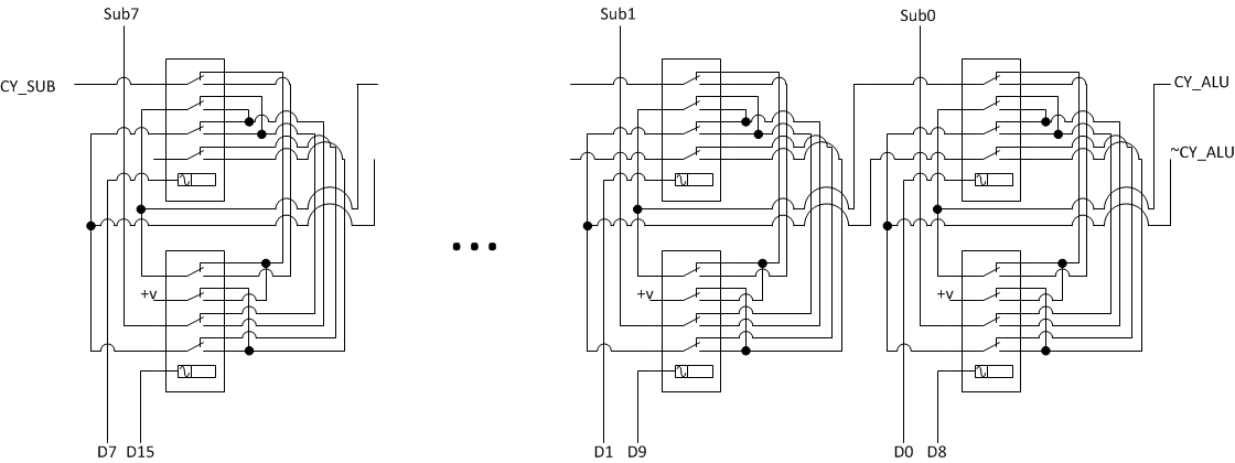
Subtractor block
Subtractor block takes two arguments, CY, and ~CY as an input and produces 8 bits of difference and one bit of Carry.
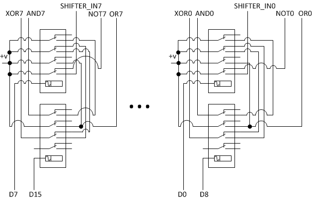
Logic block
Logic block consists of several parts:
- AND/OR/XOR/NOT block (same as in Harry Porter’s computer)
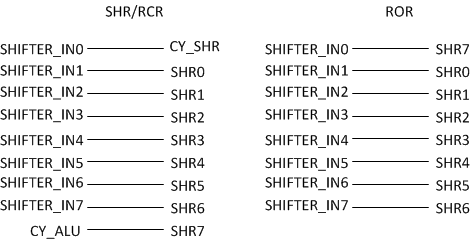
- ROR block
- SHR/RCR block
CY storage
One-bit “register” for storing CY flag has two additional relays.
One of them (Select) is used for switching CY to Adder/Subtractor/Shifter inputs.
Another one (Load) is used when CY value from the output of ALU should be stored in this “register”.
When Select is not enabled +V is passed to ~CY output to make correct adding/subtracting.

ALU result register
ALU result register is used to latch result of calculation and pass it to data bus.
It also stores CY flag to break feedback loop between Adder/Subtractor/Shifter and CY storage.
Result of calculation is loaded by LD_RES signal and selected to data bus by using SEL_RES signal.
One switch of every storage relay is used for generating Z flag which is used for conditional jumps.

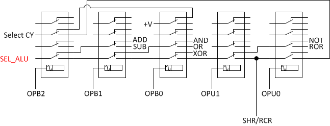
ALU operations decoder
ALU decoder takes several bits of instruction code and produces signals for selecting outputs of different ALU modules (adder, subtractor, OR, XOR, AND, shifter).
It also generates signal for selecting CY for ALU input. It is used by ADC, SBC, and RCR operations.
Enable circuits
Enable circuits are used to pass ALU blocks outputs to result register.
Output bits include 8 bits of result and CY value for Adder, Subtractor, and Shifter blocks.

Shifter circuits
Shifters do not have any relays. They contain just wires for thansferring input bits to the output of the block.